遊戯王真デュエルモンスターズ~封印されし記憶~のポケットステーションで強力なカードを入手するためのツール:チートリモコンを製作した。
今回はチートリモコンのソフトウェア設計①:動作確認を行う。
<チートリモコン作ってみたシリーズ>
・封印されし記憶を語る
・概要編
・ハードウェア編
・ソフトウェア編①:動作確認 ←いまここ
・ソフトウェア編②:キー操作
・ソフトウェア編③:チャタリング対策
・ソフトウェア編④:NECフォーマット
・ソースコード一覧
・入手カード一覧
以下の内容は、ある程度PICやC言語を知っている前提となります。
何をしているのか分からない部分があったら、参考書やwebのPIC入門などを参照してください。
まずはコンフィグについて。
基本的にMPLAB X IDEの下にあるConfigration Bitsで設定し、Generate Source Code to Outputで生成されたコードをコピーすればいい。
main.cに貼り付けると長くなるので、pic18f25k22_config.hというファイルを作成し貼り付けた。
// PIC18F25K22 Configuration Bit Settings
// 'C' source line config statements

// CONFIG1H
#pragma config FOSC = HSMP      // Oscillator Selection bits (HS oscillator (medium power 4-16 MHz))
#pragma config PLLCFG = ON      // 4X PLL Enable (Oscillator multiplied by 4)
#pragma config PRICLKEN = ON    // Primary clock enable bit (Primary clock enabled)
#pragma config FCMEN = OFF      // Fail-Safe Clock Monitor Enable bit (Fail-Safe Clock Monitor disabled)
#pragma config IESO = OFF       // Internal/External Oscillator Switchover bit (Oscillator Switchover mode disabled)

// CONFIG2L
#pragma config PWRTEN = ON      // Power-up Timer Enable bit (Power up timer enabled)
#pragma config BOREN = OFF      // Brown-out Reset Enable bits (Brown-out Reset disabled in hardware and software)
#pragma config BORV = 190       // Brown Out Reset Voltage bits (VBOR set to 1.90 V nominal)

// CONFIG2H
#pragma config WDTEN = OFF      // Watchdog Timer Enable bits (Watch dog timer is always disabled. SWDTEN has no effect.)
#pragma config WDTPS = 32768    // Watchdog Timer Postscale Select bits (1:32768)

// CONFIG3H
#pragma config CCP2MX = PORTC1  // CCP2 MUX bit (CCP2 input/output is multiplexed with RC1)
#pragma config PBADEN = OFF     // PORTB A/D Enable bit (PORTB<5:0> pins are configured as digital I/O on Reset)
#pragma config CCP3MX = PORTB5  // P3A/CCP3 Mux bit (P3A/CCP3 input/output is multiplexed with RB5)
#pragma config HFOFST = ON      // HFINTOSC Fast Start-up (HFINTOSC output and ready status are not delayed by the oscillator stable status)
#pragma config T3CMX = PORTC0   // Timer3 Clock input mux bit (T3CKI is on RC0)
#pragma config P2BMX = PORTB5   // ECCP2 B output mux bit (P2B is on RB5)
#pragma config MCLRE = EXTMCLR  // MCLR Pin Enable bit (MCLR pin enabled, RE3 input pin disabled)

// CONFIG4L
#pragma config STVREN = ON      // Stack Full/Underflow Reset Enable bit (Stack full/underflow will cause Reset)
#pragma config LVP = OFF        // Single-Supply ICSP Enable bit (Single-Supply ICSP disabled)
#pragma config XINST = OFF      // Extended Instruction Set Enable bit (Instruction set extension and Indexed Addressing mode disabled (Legacy mode))

// CONFIG5L
#pragma config CP0 = OFF        // Code Protection Block 0 (Block 0 (000800-001FFFh) not code-protected)
#pragma config CP1 = OFF        // Code Protection Block 1 (Block 1 (002000-003FFFh) not code-protected)
#pragma config CP2 = OFF        // Code Protection Block 2 (Block 2 (004000-005FFFh) not code-protected)
#pragma config CP3 = OFF        // Code Protection Block 3 (Block 3 (006000-007FFFh) not code-protected)

// CONFIG5H
#pragma config CPB = OFF        // Boot Block Code Protection bit (Boot block (000000-0007FFh) not code-protected)
#pragma config CPD = OFF        // Data EEPROM Code Protection bit (Data EEPROM not code-protected)

// CONFIG6L
#pragma config WRT0 = OFF       // Write Protection Block 0 (Block 0 (000800-001FFFh) not write-protected)
#pragma config WRT1 = OFF       // Write Protection Block 1 (Block 1 (002000-003FFFh) not write-protected)
#pragma config WRT2 = OFF       // Write Protection Block 2 (Block 2 (004000-005FFFh) not write-protected)
#pragma config WRT3 = OFF       // Write Protection Block 3 (Block 3 (006000-007FFFh) not write-protected)

// CONFIG6H
#pragma config WRTC = OFF       // Configuration Register Write Protection bit (Configuration registers (300000-3000FFh) not write-protected)
#pragma config WRTB = OFF       // Boot Block Write Protection bit (Boot Block (000000-0007FFh) not write-protected)
#pragma config WRTD = OFF       // Data EEPROM Write Protection bit (Data EEPROM not write-protected)

// CONFIG7L
#pragma config EBTR0 = OFF      // Table Read Protection Block 0 (Block 0 (000800-001FFFh) not protected from table reads executed in other blocks)
#pragma config EBTR1 = OFF      // Table Read Protection Block 1 (Block 1 (002000-003FFFh) not protected from table reads executed in other blocks)
#pragma config EBTR2 = OFF      // Table Read Protection Block 2 (Block 2 (004000-005FFFh) not protected from table reads executed in other blocks)
#pragma config EBTR3 = OFF      // Table Read Protection Block 3 (Block 3 (006000-007FFFh) not protected from table reads executed in other blocks)

// CONFIG7H
#pragma config EBTRB = OFF      // Boot Block Table Read Protection bit (Boot Block (000000-0007FFh) not protected from table reads executed in other blocks)

// #pragma config statements should precede project file includes.
// Use project enums instead of #define for ON and OFF.

#include <xc.h>
ほとんどはデフォルトのままで、主に以下を変更した。
FOSC:クロック源の選択で、外部クロック4~16MHzであるHSMPを選択。
PLLCFG:PLLでクロックを4倍にするか。4倍にするのでONを選択。
PWRTEN:電源ONから65.5ms待ってプログラムを開始するか。どっちでもいい。
BOREN:BORVで指定した電圧以下になったらリセットをかけるか。どっちでもいい。
WDTEN:一定時間以内にWDTをリセットしないとプログラム自体がリセットされる機能。使用しないのでOFFを選択。
次はmain.cだけど、一気に全部書くと長くなるのでいくつかに小分けする。
まずは#includeや#defineについて。
#include "xc.h"
#include "LCDlib.h"
#include "pic18f25k22_config.h"

#define _XTAL_FREQ 40000000

// I/O
#define RST_SW  PORTAbits.RA0
#define CUST_A  PORTAbits.RA1
#define CUST_B  PORTAbits.RA2
#define CUST_SW PORTAbits.RA3
#define DATA_A  PORTCbits.RC0
#define DATA_B  PORTCbits.RC1
#define DATA_SW PORTCbits.RC2
#define SEND_SW PORTCbits.RC3
#define LED_ON  LATB1 = 1
#define LED_OFF LATB1 = 0
上の3行はヘッダーファイルのインクルードで、xc.hはXC8コンパイラに必須。
pic18f25k22_config.hは上で作成したコンフィグファイル。
LCDlib.hはLCD関係の関数が入ったヘッダーファイルで、これは外部から入手した。
入手元は覚えていないけど、PIC関連書籍を数多く出版している後閑哲也氏のホームページか書籍の付録だったと思う。
各自で関数を作成するか、先人が公開しているヘッダーファイルを入手してほしい。
#define _XTAL_FREQ 40000000はディレイ関数を有効にするのに必須で、数値はクロック周波数を指定する。
今回は10MHz×4 = 40MHzのため、40000000を入力した。
その下の// I/Oから先は文字列の置き換え。
RA1とかRC3とか書いても分かりにくいので、分かりやすい名称に置き換えた。
スイッチ関係はプルアップしているため、押した状態で0、押していない状態で1になる。
ここからがint main()で、以下のプログラムはこの中に書いていく。
これは自動生成されたもの。
int main() {

  return (EXIT_SUCCESS);
}
まずはI/Oポートの定義。
回路図を見て、ANSEL○でアナログ/デジタルの定義、TRIS○で入力/出力の定義をする。
  // I/O Port Init
  ANSELA = 0x00; //全てデジタル
  ANSELB = 0x00; //全てデジタル
  ANSELC = 0x00; //全てデジタル
  TRISA  = 0xCF; //RA7-6,3-0が入力
  TRISB  = 0x00; //RB7-0が出力
  TRISC  = 0x0F; //RC3-0が入力
次はLCDの初期化。
筆者が使っているLCDlib.hでは、主に2つの関数を使用する。
void lcd_init(void):LCDの初期化。
void lcd_str(int ten, int one, char *str):文字列を書き込む関数。tenとoneで1文字目の座標を選択し、*strに入力した文字列を書き込む。
LCDの座標とアドレスの関係は以下のようになっている。
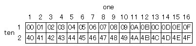
ここでの注意点は、1行目のラストが0x0Fに対し2行目のアドレスが0x40で始まっており、その間(0x10~0x3F)は表示されない。
lcd_strの内部をイジれば繋がるようにできるが、基本的には1行ずつ書くようにしたほうがいい。
実際に書いたのは以下の通り。
  // LCD Init
  lcd_init();
  lcd_str(1, 1, "NEC  Custom Data");
初期化後、1行目の1文字目からNEC Custom Dataを書き込む。
プログラムの基本だとHello Worldを書くのが相場だが、本番に合わせた。
Main Loopでは、各種スイッチの状態を監視し、入力されたスイッチをLCDに表示させてみた。
また、SENDスイッチを押した場合はLEDも点灯するようにした。
  // Main Loop
  while(1){
    // Keys
    if(RST_SW == 0){
      lcd_str(2, 1, "Reset SW Push   ");
      __delay_ms(500);
    }
    else if((CUST_A == 0) && (CUST_B == 1)){
      lcd_str(2, 1, "CUST ENC CW     ");
      __delay_ms(500);
    }
    else if((CUST_A == 1) && (CUST_B == 0)){
      lcd_str(2, 1, "CUST ENC CCW    ");
      __delay_ms(500);
    }
    else if(CUST_SW == 0){
      lcd_str(2, 1, "CUST ENC SW Push");
      __delay_ms(500);
    }
    else if((DATA_A == 0) && (DATA_B == 1)){
      lcd_str(2, 1, "DATA ENC CW     ");
      __delay_ms(500);
    }
    else if((DATA_A == 1) && (DATA_B == 0)){
      lcd_str(2, 1, "DATA ENC CCW    ");
      __delay_ms(500);
    }
    else if(DATA_SW == 0){
      lcd_str(2, 1, "DATA ENC SW Push");
      __delay_ms(500);
    }
    else if(SEND_SW == 0){
      lcd_str(2, 1, "SEND SW Push    ");
      LED_ON;
      __delay_ms(500);
    }
    else{
      LED_OFF;
    }
  }
前述の通り、各種スイッチは0が押した状態となる。
ロータリーエンコーダーはA相とB相の2個のスイッチがあり、CW(時計回り)だとAが先に押され、CCW(反時計回り)だとBが先に押される。
以上のプログラムを書き込み、動作確認してみた。
全て正常に動作しているが、動作確認用に最低限の処理しかしていないため、エンコーダーは時々逆回転になっていた。
赤外線LEDはこんな感じ。
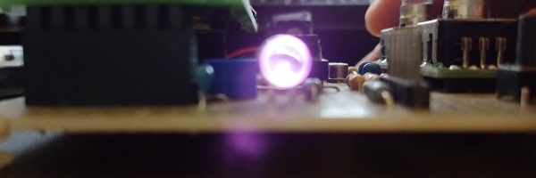
肉眼では見えないが、カメラのセンサーには反応するので見ることができる。
次回はスイッチに具体的な機能を追加する。
また、エンコーダーをロジックアナライザで解析し、チャタリングやゆっくり回転させても誤動作しないようにしてみる。